Dec. 05, 2023
When the system working pressure is not greater than 1.20MPa, ductile iron pipes or steel mesh frame plastic composite pipes should be used for water supply pipes; when the system working pressure is greater than 1.20MPa and less than 1.60MPa, steel mesh frame plastic composite pipes, thickened steel pipes and Seamless steel pipe; when the system working pressure is greater than 1.60MPa, seamless steel pipe should be used.
When the system working pressure is less than or equal to 1.20MPa, hot-dip galvanized steel pipes can be used; when the system working pressure is greater than 1.20MPa, hot-dip galvanized thickened steel pipes or hot-dip galvanized seamless steel pipes should be used; when the system working pressure When it is greater than 1.60MPa, hot-dip galvanized seamless steel pipe should be used.
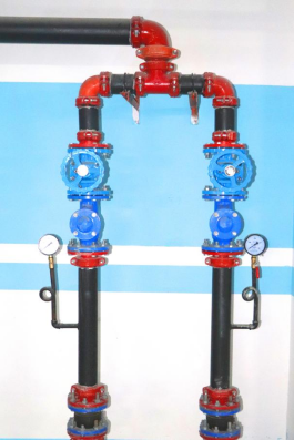
① The valves of buried pipelines should use hidden stem gate valves with opening and closing scales. When installed in the valve well, corrosion-resistant rising stem gate valves can be used.
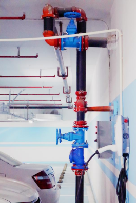
② The valves for indoor overhead pipelines should be butterfly valves, rising stem gate valves or concealed stem gate valves with opening and closing scales, etc.
③ Outdoor overhead pipelines should use concealed stem gate valves with opening and closing scales or corrosion-resistant rising stem gate valves.
④ The valves of buried pipelines should be ductile iron valves, the valves of indoor overhead pipelines should be ductile iron or stainless steel valves, and the valves of outdoor overhead pipelines should be ductile iron valves or stainless steel valves.
⑤An automatic exhaust valve should be installed at the highest point of the fire water supply system pipeline.
⑥The check valve on the outlet pipe of the fire water pump should use a water hammer elimination check valve. When the water supply height of the fire water pump exceeds 24m, a water hammer eliminator should be used. When the fire water pump outlet pipe is equipped with a bladder-type air pressure water tank, water hammer elimination facilities are not required.

1) When two-channel fire-fighting water supply is used for outdoor fire-fighting water supply, annular pipe network should be used, but when one-channel fire-fighting water supply is used, branch-shaped pipe network can be used.
2) There should be no less than two water inlet pipes that deliver water to the annular pipe network. When one of them fails, the remaining water inlet pipes should be able to meet the total supply requirements for fire water.
3) The diameter of the pipe should be calculated and determined based on the flow, flow rate and pressure requirements, but should not be less than DN100.
4) The fire water supply pipeline should be divided into several independent sections using valves, and the number of indoor and outdoor fire hydrants in each section should not exceed 5.

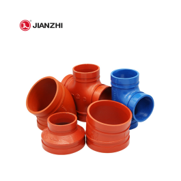
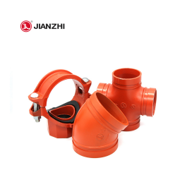
JIANZHI Grooved Pipe Fittings
1) The pipe network of the indoor fire hydrant system should be arranged in a ring shape. When the design flow rate of the outdoor fire hydrant is not greater than 20L/s and there are no more than 10 indoor fire hydrants, it can be arranged in a branch shape unless there are special requirements.
2) When the water supply is directly provided by the outdoor production and living fire-fighting shared system, the shared system should not only meet the design flow requirements of the outdoor fire-fighting water supply and the maximum hourly design flow requirements for production and living, but also meet the design flow and pressure requirements of the indoor fire-fighting water supply system.
3) The diameter of the indoor fire hydrant standpipe should be calculated and determined based on the minimum flow rate of the standpipe, but should not be less than DN100.
4) The following regulations should be met during maintenance of indoor fire hydrant ring water supply pipelines:
① Indoor fire hydrant vertical pipes should ensure that no more than one vertical pipe is closed and out of service during pipeline maintenance. When there are more than four vertical pipes, two non-adjacent vertical pipes can be closed.
② A valve should be installed at the junction of each vertical pipe and the horizontal main water supply pipe.
The design flow rate of fire water supply pipelines should not be greater than 2.5m/s, and the water supply velocity of any fire protection pipeline should not be greater than 7m/s.

Pipe fittings application scenarios
1) When fire water supply pipes pass through basement exterior walls, building walls, roofs and other places with waterproofing requirements, waterproof casings should be installed.
2) When the fire water supply pipe passes through the load-bearing wall or foundation of the building, a hole should be reserved. The height of the hole should ensure that the clearance at the top of the pipe is not less than the settlement of the building, which should not be less than 0.1m, and should be filled with impermeable elastic materials.
3) When the fire water supply pipe passes through the wall or floor, a casing should be added. The length of the casing should not be less than the thickness of the wall, or should be 50mm higher than the floor or ground; the gap between the casing and the pipe should be filled with non-combustible materials. Connections to pipes should not be located within casing.
4) When fire water supply pipes must pass through expansion joints and settlement joints, technical measures such as bellows and compensators should be used.
5) The outside of the pipeline should be painted with red paint or a red ring mark, and the name of the pipeline and the direction of the flow should be marked. The width of the red ring mark should not be less than 20mm, the interval should not be greater than 4m, and there should be no less than 2 rings in an independent unit.
1) The designed hanger should be able to withstand 5 times the weight of the pipe filled with water at each support point of the pipeline, and the support points of the pipeline system should support the entire fire water supply system.
2) The support points of the pipe supports should be located on the structure of the building. The structure should be able to withstand the weight of the water-filled pipes plus at least 114kg of additional loads such as valves, flanges and joints at the pipe suspension points.
3) When the pipeline is installed through a beam, the beam penetration should be used as a hanger.
4) The following parts should be equipped with fixed brackets or anti-sway brackets:
① The water distribution pipe should be equipped with an anti-sway bracket at the midpoint, but it is not necessary when the pipe diameter is less than DN50.
② For water distribution main pipes, water distribution pipes, and water distribution branch pipes whose length exceeds 15m, at least one anti-sway bracket should be installed within every 15m of length, but it is not necessary when the pipe diameter is not larger than DN40.
③An anti-sway bracket should be installed at the corners, tees and crosses of pipelines with a diameter larger than DN50.
④ The strength of the anti-sway bracket should be such that the weight of the pipe, fittings and water in the pipe plus 50% of the horizontal thrust will not cause damage or permanent deformation; when the pipe is installed through a beam, the pipe should be fixed to the concrete with fasteners Structurally, it should be treated as an anti-sway bracket.

Pipe fittings application scenarios
1) After the pipe network is installed, strength test, flushing and tightness test should be carried out.
2) The strength test and tightness test should be conducted with water. Dry fire hydrant systems should undergo hydraulic and air pressure tests.
3) After the system pressure test is completed, all temporary blind plates and test pipes should be removed in time, and the records should be checked for accuracy.
4) Pipe network flushing should be carried out in sections after passing the pressure test. The order of flushing should be outdoor first, then indoors; first underground, then above ground; the flushing of indoor parts should be carried out in the order of water supply main pipes, horizontal pipes and vertical pipes.
5) The following conditions should be met before system pressure test:
① The location of the buried pipeline and the pipeline foundation, buttresses, etc. shall meet the design requirements upon review.
② The number of pressure gauges used for pressure testing should not be less than 2; the accuracy should not be lower than level 1.5, and the measuring range should be 1.5 to 2 times the test pressure value.
③The pressure test flushing plan has been approved.
④ Equipment, instruments, valves and accessories that cannot participate in the pressure test should be isolated or removed; the additional temporary blind plates should have ears protruding from the flange and should be clearly marked, and the number of temporary blind plates should be recorded.
6) During the system pressure test, when leakage occurs, the pressure test should be stopped, and the test medium in the pipe network should be emptied. After the defects are eliminated, the test should be repeated.
7) Pipe network flushing should be done with water. Before flushing, protective measures should be taken for the system's instruments.
8) Before flushing, the pipeline anti-sway brackets, supports and hangers should be inspected, and reinforcement measures should be taken if necessary.
SAFER
PRODUCT INFO
ABOUT JIANZHI
TECH DATA
Contact Us
E-mail: sales1@jianzhi-fitting.com
Tel: +86 18698027872
Office In Tianjin:
Heping District, Tianjin, China.
Production Base 1:
Chifeng, Inner Mongolia, China.
Production Base 2:
Tangshan City, Hebei Province, China.
Production Base 3:
Schelei Street,Baicoi City,Prahova County,Romania
Service email: info.ro@jianzhi-fitting.com
Sales email: market.ro@jianzhi-fitting.com
Tel: +40(755)011 849
